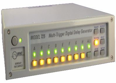
The Model 725 hardware controller can operate in stand-alone mode or via computer control. The computer control system uses its own user-friendly software, timerPRO or LabView,™ both tested and proven in many experiments. timerPRO makes it easy to create sophisticated control schemes from your PC. With the Model 725 linked to your computer, you’ll quickly program, refine and expand experiments. Using stand-alone mode, you can store and recall up to 64 complete settings, then trigger and monitor an experiment from the Model 725’s front panel. You’ll have the flexibility to design experiments offline, then to embed the controller in your test environment for “set and forget” operation. The firmware in the Model 725 is field upgradeable, allowing access to new timing modes and capabilities as they become available. timerPRO’s opening window summarizes the settings and lets you alter them.
Complex Timing Sequences with Digital Delays
A precision Digital Delay Generator such as the BNC Model 575 uses a single or dual trigger with a common clock to synchronize multiple events and cannot be re-triggered until the completion of the longest timed event. The Model 725 addresses a matrix of timing issues with 8 triggers, 8 timers and 8 outputs. The triggering of each of these timers is independent of the other timers. The triggers can be logical combinations of inputs and outputs – AND’s, OR’s, XOR’s and Negated. Also any number of timers can be triggered together to function as a traditional multi-channel digital delay generator with sub-uS timing.
Some applications examples
Fluid dynamics:
In a two-pulse experiment, two lasers were fired in rapid succession to illuminate and capture successive snapshots of a high speed fluid flow. The Model 725 handled all aspects of the experiment, from warming up the lasers to precisely timing the nanosecond- scale pulses. Using the Model 725’s onboard logic and software interface, the experimenters implemented special “alignment” and “calibration” modes for preparing the experiment and “laser ready” interlocks for safety.
High speed gas flow:
A combustion-driven shock tube was used to study high speed gas flows. The Model 725 was the heart of the experiment, taking charge of ignition, pressure sensing, detonation, laser timing, data acquisition and more complex, interrelated timing sequences were orchestrated on the PC using the virtual front panel software.
Experiment Inputs: Control panel switches, pressure transducers, accelerometers, ionization gauges, safety interlock, computer commands.
Experiment Outputs: Shutter, Camera, Laser Flashlamp, Laser Q-Switch, Data Acquisition, Oscilloscope, Diaphragm Burster, Igniter.
|


